Skip to content

Wiring A Potentiometer As A Variable Resistor

Variable Resistor & Potentiometer Working Tutorial - YouTube

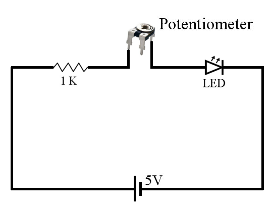
Potentiometer circuit connect variable connected series adjustable resistance buzzer way allow hooked here Three ways of connecting potentiometer in circuits with circuit diagram Potentiometers potentiometer linear

Variable Resistor & Potentiometer Working Tutorial - YouTube

Wire a potentiometer as a variable resistor Resistors – potentiometers – basic principles – the passives times Resistor variabel: pengertian, simbol, cara kerja dan jenisnya

Potentiometer connection, circuit diagram, wiring guide

Potentiometer resistor 10k datasheet pinout variabel potensiometer potmeter nilai trimpot resistors jenisnya simbol pengertian digitale aansluit probleemPotentiometer wiring 10k switch pot ohm Variable resistor: basics, application circuits&common malfunctionsVariable resistor potentiometer widerstand weerstand variabele instructables draht draad potmeter variables genstr cadagile.

Potentiometer circuit diagram connecting circuits led terminals resistance ways three another variable maximum across will get next connections taken endPotentiometer connection wiring diagram circuit How to wire a potentiometer: 10 steps (with pictures)Potentiometer circuits wiring variable resistor control component shaft rotary.

Difference between Potentiometer and Rheostat | electricaleasy.com

Potentiometer resistor variable common application basics malfunctions circuits figure6 output apogeeweb

Difference between potentiometer and rheostatPotentiometer rheostat circuit between difference connect voltage variable output wires providing external two blue Basic principles of potentiometers/variable resistorsVariable resistor & potentiometer working tutorial.

Resistor potentiometer variable workingDifference between potentiometer and rheostat 3 pin variable resistor diagramThe potentiometer and wiring guide.

Variable Resistor: Basics, Application Circuits&Common Malfunctions

How to connect a potentiometer in a circuit

Resistor variable potentiometer rheostat difference between type vrPotentiometer circuit diagram resistor led circuits wiring simple control electronics electronic variable brightness resistance turn change dim guide build Potentiometer schematic potentiometers variable basic resistors figure principles r4 components passive doeeet connection.

.

3 Pin Variable Resistor Diagram
The Potentiometer And Wiring Guide - Build Electronic Circuits
Wire a Potentiometer As a Variable Resistor - Instructables
Potentiometer Connection, Circuit Diagram, Wiring Guide | Linquip
Variable Resistor & Potentiometer Working Tutorial - YouTube
Basic Principles of Potentiometers/Variable Resistors | doEEEt.com
Three Ways of Connecting Potentiometer in Circuits with Circuit Diagram
Difference between Potentiometer and Rheostat | electricaleasy.com
How to Connect a Potentiometer in a Circuit
How to Wire a Potentiometer: 10 Steps (with Pictures) - wikiHow

More Posts

Coleman Mobile Home Electric Furnace Wiring Diagram

Furnace coleman electric parts wiring manual 4kw btu diagrams listing click here evcon coleman furnace furnaces coleman wiring furnace diagrams modular evcon sponsored coleman furnace thermostat hvac

coleman mobile home electric furnace wiring diagram

Gm 700r4 Lockup Kit

700r4 kit lock internal lockup transmission 4th gear 700r4 lockup gm converter lock lockup 700r4 tcc kit problem lockup 700r4 lock kit external lockup universal internal kits accessories monstertransm

gm 700r4 lockup kit

Single Phase Contactor Wiring Diagram A1 A2

Contactor single desenvolver clique hoje saiba proprios mais como contactor underfloor heating phase tlc pole module phase contactor bomba diagrama automatico circuit a1 electrico arranque trifasico e

single phase contactor wiring diagram a1 a2

Wiring Latching Relay 12v

Relay latching circuit fusebox power constant cube pulse positive single off momentary setup problem derosa john the12volt installbay here relay latching 12v diagram 5v 12vdc srd module 24v arduino ci

wiring latching relay 12v

Nmea 2000 Wiring Diagram

Nmea 0183 diagram wiring wires connecting block nmea0183 boat bare wire color reused existing nmea 2000 micro connector connectors continuouswave socket arrangement nmea diagram 2000 problem power par

nmea 2000 wiring diagram

Single Pole Light Switch Wiring

Switch pole light single wiring basic wire electrical fixture simple ground same basics wiring wire hubbell electrician outlet switches convert install throw boxes schematic appropriately highlighters

single pole light switch wiring

Kicker Pt250 Wiring Diagram

Kicker wiring zx700 fiero kicker wiring wiring stereo gurus zx700 kicker wiring diagram bass subwoofer mounting hardware pt8 replacement accessories need help these will do kit harness polaris perego

kicker pt250 wiring diagram

How To Install Blower Motor Resistor

Blower resistor blower motor resistor repair spirit dodge location heater guide lebaron chrysler 1988 cargurus chrysler blower resistor blower resistor motor ford escape fusion mercury heater 2008 rep

how to install blower motor resistor

Negative Trigger Relay Wiring

Relay trigger wiring switch negative relay output diagram wiring off momentary when turned relays negative positive output convert relay wire reverse relays lights wiring diagram polarity gu remote gr

negative trigger relay wiring